


Price: €11,70
(as of Jan 01, 2026 18:40:30 UTC – Details)
Product Description

Step 1: Install 3pcs 150ohm metal film resistors at R2,R4,R6 on CTR-30A. Note: The smaller the resistor value, the brighter the LED. R2/R4/R6 can be 0~470ohm. So user can replace resistor with 0ohm metal wires which can cut extra pins from others components.
Step 2: Install 3pcs 10Kohm metal film resistors at R1,R3,R5 on CTR-30A.

Step 3: Install 1pcs 470ohm Metal Film Resistors at R7 on CTR-30A.
Step 4: Identify the positive(anode) and negative(cathode) lead of LED.The leads of the LED must be installed correctly, otherwise the LED cannot be turned on.Here are four methods as following:
4.1 According to the length of the LED lead to distinguish. The longer pin is positive(anode) lead.
The shorter pin is negative (cathode) lead.
4.2 Identify the negative(cathode) of the LED is to look into the plastic case where one can see that the negative(cathode) is much thicker/bigger inside the plastic case than the anode lead.
4.3 Identify by edge of plastic case.The negative(cathode) lead of the LED should be the pin nearest the flat on the plastic case.
4.4 Test by 3V battery or multimeter.The pin is positive(anode) lead which has connect to the positive of 3V if LED can light up after connect 3V power supply. (LED should not be powered directly from the 3V for a short time:less then 0.5second)
4.5 It is positive(anode) where the white mark “ + “ pointing to on PCB.

Step 5: Pay attention to the placement of the LED and then install 18pcs 3mm RGB LED at D1-D18 on CTR-30A and bend the metal pins of the LED as shown for easy mounting. The square pad is the positive pole.
Step 6: Install 3pcs 47uF 16V Electrolytic Capacitor at C1,C2,C3 on CTR-30A. Pay attention to distinguish between positive and negative. The Longer pin is positive pole. Note: The capacitor needs to be placed horizontally which in order to facilitate the splicing of PCB later.

Step 7: Install 3pcs TO-92 S9014 transistor at Q1,Q2,Q3 on CTR-30A then bend again which in order to facilitate the splicing of PCB later. Pay attention to the installation direction. The arc on the PCB corresponds to the arc of the components.
Step 8: Install 3pcs 150ohm metal film resistors at R2,R4,R6 on CTR-30B. Note: The smaller the resistor value, the brighter the LED. R2/R4/R6 can be 0~470ohm.So user can replace resistor with 0ohm metal wires which can cut extra pins from other components.

Step 9: Install 3pcs 10Kohm metal film resistors at R1,R3,R5 on CTR-30B.
Step 10: Pay attention to the placement of the LED and then install 18pcs 3mm RGB LED at
D1-D18 on CTR-30B and bend the metal pins of the LED as shown for easy mounting. The square pad is the positive pole.

Step 11: Install 3pcs 47uF 16V Electrolytic Capacitor at C1,C2,C3 on CTR-30B. Pay attention to distinguish between positive and negative. The Longer pin is positive pole. Note: The capacitor needs to be placed horizontally which in order to facilitate the splicing of PCB later.
Step 12: Install 3pcs TO-92 S9014 transistor at Q1,Q2,Q3 on CTR-30B then bend again which in order to facilitate the splicing of PCB later. Pay attention to the installation direction. The arc on the PCB corresponds to the arc of the components.

Step 13: Splicing CTR-30A and CTR-30B, pay attention to align the fixing points, and then fix it with solder tin wire. Pay attention to the splicing direction.
Step 14: Install 1pcs 3.5mm DC Socket at J1. Tops: Secure the socket with metal wire which cut from components.

Step 15: Install 1pcs 5.8*5.8mm Self-locking Switch at S1.
Step 16: Fix 1pcs AA*3 battery box by 2pcs M2*8mm and 2pcs M2 Nut.

Step 17: Connect battery wire: Red connect to + and black wire connect to – .Cut the excess wire.
Step 18: Fix PCTR-30A and CTR-30B on PCTR-30C. Pay attention to the direction of positive and
Negative pole. Align each pad and horizontally vertically. Then fix each pad.
Step 19: Install 1pcs 3mm RGB LED at top. Pay attention to the direction of positive and negative pole.
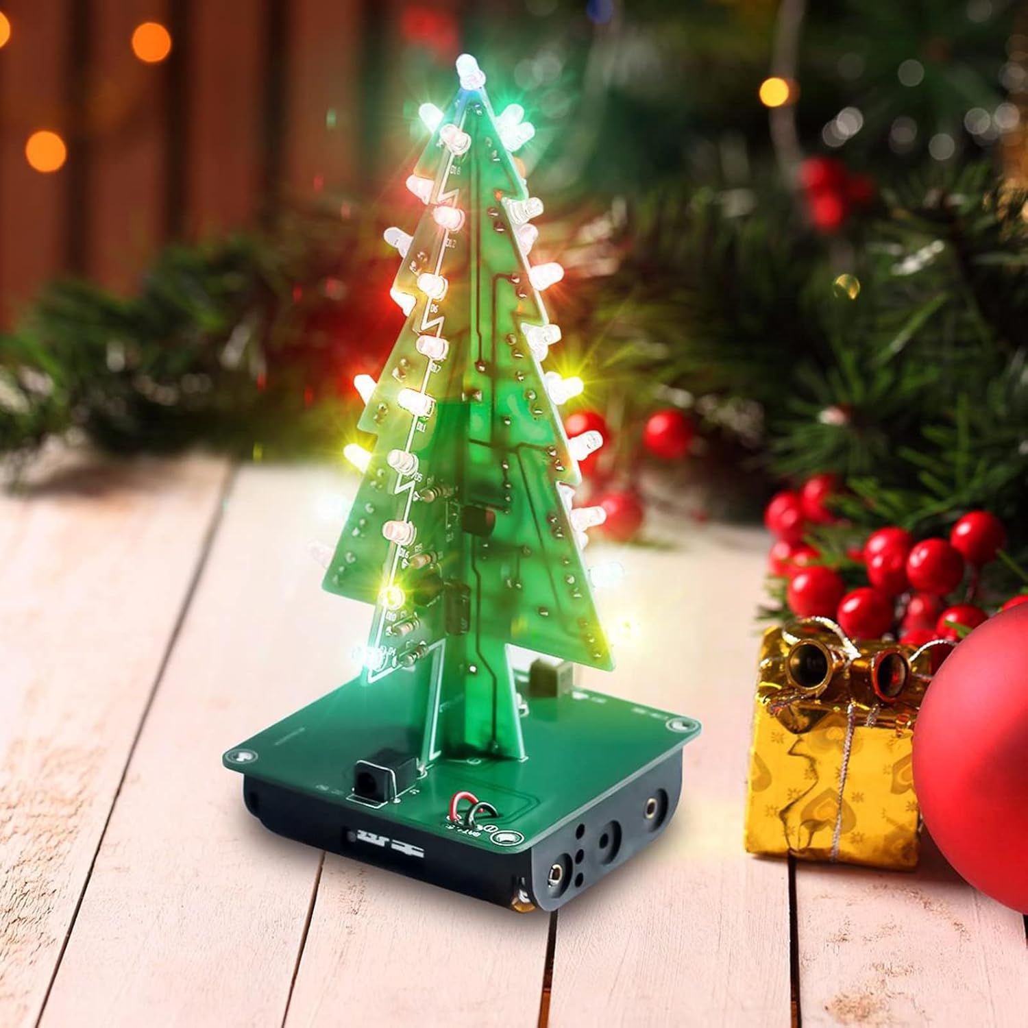
DIY fun: 3D Christmas tree consists of different boards and parts as shown in the picture. Perfect for soldering practice
Christmas gift: 36 colourful LEDs (red, blue, yellow) present a creative gift or a beautiful decoration especially at Christmas.
Light: DC 4.5 V-5 V working voltage can be operated directly with 3 x AA batteries or USB power supply
Gifts: Self-built LED Christmas tree for family or friends
Size: 60 x 60 x 136 mm